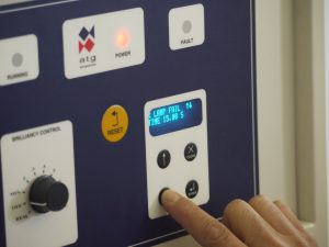
The Micro200 Constant Current Regulator (CCR) is used for powering airfield lighting circuits, and is manufactured by atg airports. The Micro 200 CCR complies with EN 61822:2009 – Electrical installations for lighting and beaconing of aerodromes – Constant current regulators, and all applicable EMC standards.
Micro200 CCR Installation Guide
Product Overview
Introduction
For optimum performance the CCR is required to be configured to ensure that it matches the load of the field circuit. This article will talk through the basic steps of the CCR set up but for more detailed information reference should be made to the manual.
DANGER – HIGH VOLTAGE CIRCUITRY
This equipment employs high voltage circuitry within the cubicle – up to 5000V for a 30kVA regulator – that presents a hazard of fatal electric shock should personnel come into contact with or close proximity to the conductors.
Installation and servicing of the CCR should only be undertaken by suitably qualified personnel who are familiar with this type of equipment. Extreme caution should be exercised when working on the CCR.

Sizing of the CCR
The CCR should be sized to match the circuit requirements. To calculate the size of the CCR required the total lamp load needs to be considered, the length of the AGL circuit and any extra long secondary cables that may be on the circuit.
The basic formula for this is : (((Total lamp wattage + AGL tx secondary extension lead I2R losses) x 1.1) + (I2R power loss in the AGL primary series loop cable))) x 1.1
This load calculations give a value in kilowatts, whilst the CCR is rated in kVA. These figures can be considered to be equivalent for the purposes of rating the CCR.
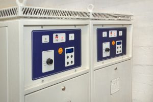
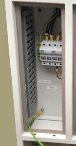
Mains supply Input
This terminal box contains the mains supply fuses or circuit breaker and the control supply fuses. Cable entry is via the gland plate at the bottom of the box; the incoming mains cables connect directly into the fuse carriers (or circuit breaker), to the terminals marked “L1” and “L2”. The supply cable cross sectional area should be sized according to the rating of the CCR.
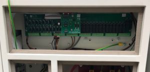
Control connections
If the CCR is to be hard wired to the AGL control system then the control cable will terminate via screw connectors on the main Relay I/O Cards
Optional serial communications modules are available to give Remote Control using Profibus, Modbus TCP/IP or J-BUS. These modules would normally be fitted instead of the Relay I/O Cards
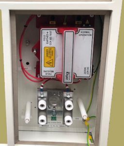
HT Series Circuit Output Terminals
Warning – high voltages – up to 5000v for a 30kva regulator – may be present within the HT terminal box. The cover to this compartment should never be opened without first isolating the regulator mains supply input.
Before the AGL field cables and CCR output terminals are safe to touch, they should be shorted together and connected to earth, preferably using a suitable switching device (Series Cut-Out Switch). Residual charge or induced emf from other AGL circuits may otherwise present a hazard to personnel
Commissioning
The factory test of the Micro 200 CCRs includes accurate calibration of the CCR output current level. This is performed using a specialised, calibrated, power analyser. Re-calibration of the regulator should not therefore, be undertaken as part of the commissioning process.
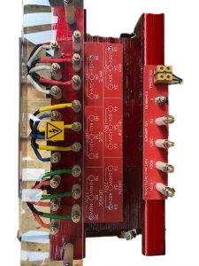
Set the CCR Main Transformer input voltage taps to suit the local supply, for example 380v, 400v or 415v. Set the Transformer output voltage taps to correctly match the series circuit load.
When the regulator has been correctly configured it is ready for initial power up.
Setting of parameters
The CCR has a default configuration when supplied from the factory. These parameters can be altered via the front panel menu. For more detailed information on the different settings reference to the user manual should be made.
ATG airport provides a full commissioning services and should you require to take advantage of this service please contact enquiries@atgairports.com ref : CCR commissioning.
